

AIRCRAFT CONFIGURATION DESIGN AND COMPONENT INTEGRATION
Abstract
Abstract
Abstract
This report presents a combined aerodynamic and structural investigation of multiple aircraft components. Computational Fluid Dynamics (CFD) simulations were conducted using ANSYS Fluent to evaluate the aerodynamic behaviour of a NACA 2412 front wing and a NACA 0012 vertical tailfin under subsonic flow conditions. Parameters assessed include lift force, drag force, surface pressure distribution, velocity wake formation, and aerodynamic efficiency (L/D ratio).
Structural analyses of the fuselage were performed in ANSYS Mechanical using finite element methods, examining total deformation, von Mises stress, and von Mises strain under both uniform pressure loading and wing-root force applications. A crank-rocker four-bar mechanism for landing gear actuation was also studied kinematically. The results provide validated insight into aerodynamic performance and structural integrity relevant to lightweight aircraft applications.
Gmeet-https://meet.google.com/jex-wykv-zsx
Aim
The aim of this project was to conduct a comprehensive aerodynamic and structural analysis of key aircraft components using industry-standard simulation tools. The study focused on:
Evaluating the lift and drag characteristics of the NACA 2412 front wing and NACA 0012 tailfin via CFD simulation.
Comparing aerodynamic coefficients with theoretical expectations to validate simulation fidelity.
Characterising pressure distribution, wake formation, and boundary layer behaviour around each aerofoil profile.
Investigating fuselage structural response — deformation, stress, and strain — under pressure and wing-root loading scenarios.
Analysing the kinematics of a crank-rocker four-bar mechanism applied to aircraft landing gear actuation systems.
Introduction
Modern aircraft design demands a rigorous balance between aerodynamic efficiency and structural integrity. Wing aerofoil selection directly governs lift generation capacity, drag penalty, and flow separation behaviour — factors that collectively determine aircraft range, endurance, and fuel efficiency. The NACA family of aerofoils, developed by the National Advisory Committee for Aeronautics, remains one of the most widely referenced profiles in both academic research and practical aircraft design due to its well-characterised aerodynamic behaviour.
The NACA 2412 aerofoil, with 2% maximum camber and 12% thickness-to-chord ratio, is a cambered profile that generates positive lift at zero angle of attack — making it well-suited for main wing applications where consistent lift generation is essential. The NACA 0012, a symmetric profile with zero camber, is the established standard for vertical stabiliser design, where aerodynamic neutrality at zero sideslip is required.
Beyond aerodynamics, the fuselage forms the primary load path of an aircraft, transferring aerodynamic, inertial, and ground loads between the wings, empennage, and landing gear. Understanding its deformation and stress distribution under realistic loading conditions is essential for safe, weight-efficient structural design. Landing gear mechanisms, particularly crank-rocker four-bar linkages, must provide reliable and compact actuation through the full deployment and retraction cycle.
This project employs Computational Fluid Dynamics (CFD) in ANSYS Fluent and Finite Element Analysis (FEA) in ANSYS Mechanical to investigate each of these components systematically. A SolidWorks CAD model was used to define the fuselage geometry for structural simulation.
Methodology
Aerofoil selection and geometry-
Two aerofoil profiles were selected for CFD analysis — the NACA 2412 for the front wing and the NACA 0012 for the vertical tailfin. Standard NACA coordinate data was used to generate aerofoil profiles, which were then imported into ANSYS DesignModeler to construct three-dimensional wing geometries. A cuboidal fluid domain was established around each wing, with a Boolean subtraction used to define the fluid region.
NACA 2412 — Front Wing Specifications
Aerofoil: NACA 2412 (2% camber, 12% thickness-to-chord ratio)
Span: 3 m
Angle of Attack: 0°
Reference Wing Area: 0.404 m² (Bell-Shaped Lift Distribution configuration)
NACA 0012 — Tailfin Specifications
Aerofoil: NACA 0012 (symmetric, zero camber, 12% thickness-to-chord ratio)
Chord Length: 1 m | Wingspan: 1 m
Angle of Attack: 0°
Domain: X: +10 m / −5 m; Y: ±5 m; Z: ±5 m
Meshing-
“A mesh sensitivity study was performed to ensure aerodynamic coefficients varied negligibly with further mesh refinement.”
For the NACA 2412 front wing, an unstructured automatic mesh was generated with local surface refinement near the aerofoil boundary layer to accurately capture pressure gradients and viscous effects. For the NACA 0012 tailfin, a base element size of 0.4 m was used with additional face sizing refinement of 0.2 m at the wing surface. Named selections — Inlet, Outlet, Wing, and Wall — were defined in both models for boundary condition assignment
CFD Solver Configuration — ANSYS Fluent-
The following solver configurations were applied for each aerofoil:
Governing Equations-
Aerodynamic force coefficients are defined as:
C_L = L / (0.5 · ρ · V² · S) [Coefficient of Lift]
C_D = D / (0.5 · ρ · V² · S) [Coefficient of Drag]
where L = lift force (N), D = drag force (N), ρ = air density (kg/m³), V = freestream velocity (m/s), S = reference planform area (m²). Force values were extracted using ANSYS Fluent function calculators post-convergence.
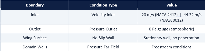
Boundary Conditions-
Fuselage CAD & Structural Setup-
A representative fuselage shell (2 mm wall thickness) was modelled in SolidWorks and imported into ANSYS Mechanical for FEA. The material assigned was Aluminium 7570, representing an aerospace-grade lightweight alloy. Two loading scenarios were investigated: (1) uniform pressure loading at 0.5 MPa, 1 MPa, and 50 MPa with a fixed tail constraint, and (2) a wing-root loading of 100 N force and 1 N·m torque applied to a face-split region.
Results-
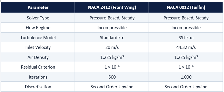
1. NACA 2412 Front Wing — CFD Results (ANSYS Fluent)-
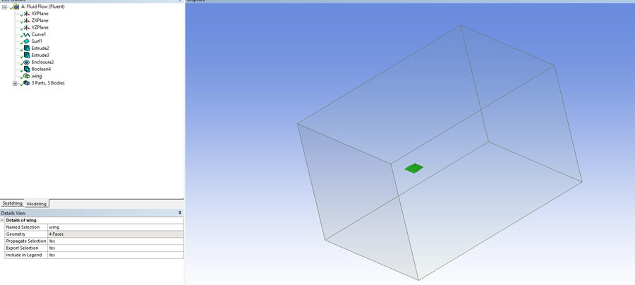
Figure 2 — Surface pressure contour: high-pressure concentration at the leading edge
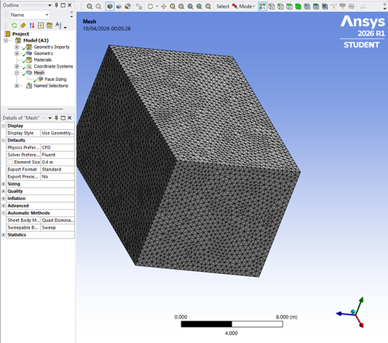
Figure 3 — Velocity streamlines showing boundary layer development and wake region
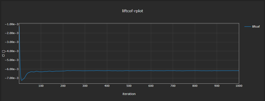
Figure 4 — Pressure coefficient (Cp) distribution along the chord
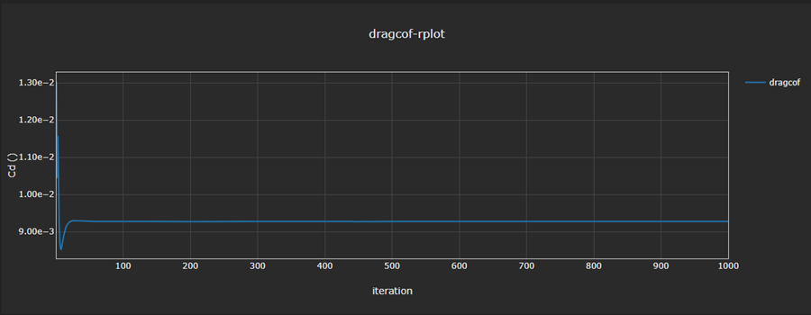
Figure 5 — Lift and drag force convergence history
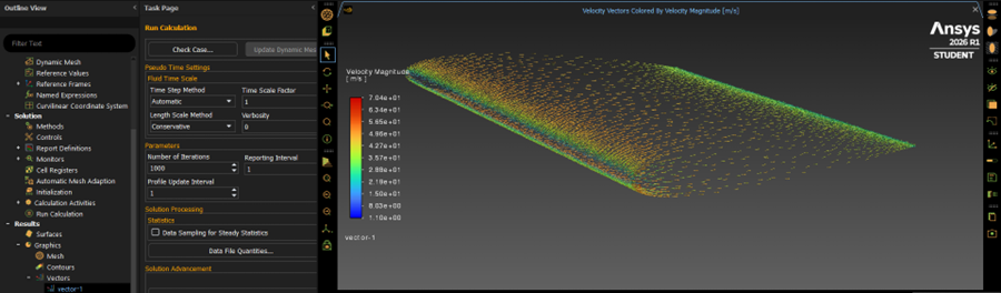
Figure 6 — Velocity magnitude contour around the NACA 2412 profile
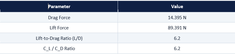
Aerodynamic Force Results-
Key Observations-
- High static pressure concentrates near the stagnation point at the leading edge on the lower surface.
- A low-pressure region develops on the upper surface near the trailing edge, generating the pressure differential responsible for lift.
- Wake formation is clearly visible downstream, consistent with viscous boundary layer detachment.
- The cambered profile generates stable positive lift at zero angle of attack, confirming expected aerofoil behaviour.
- The L/D ratio of 6.2 is consistent with NACA 2412 theoretical performance at subsonic, low-incidence conditions
2. NACA 0012 Tailfin — CFD Results (ANSYS Fluent)-
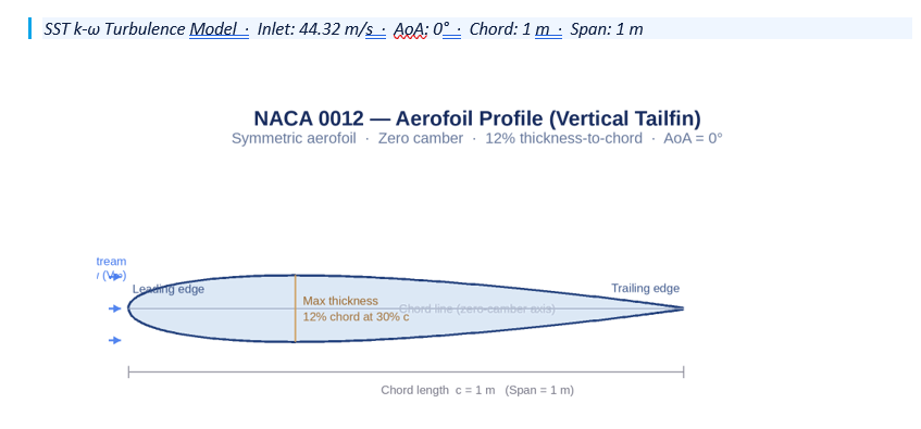
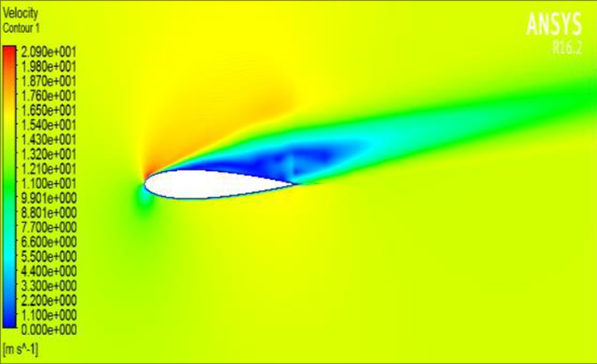
Figure 7 — NACA 0012 aerofoil profile: symmetric geometry, zero camber, 12% thickness-to-chord ratio
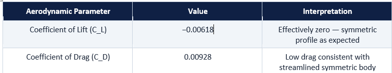
Aerodynamic Coefficient Results-
Key Observations-
- The lift coefficient is effectively zero (−0.006), confirming the NACA 0012’s aerodynamic neutrality at zero sideslip — the defining requirement for a vertical stabiliser.
- The SST k-ω turbulence model accurately captures the attached flow regime and near-wall boundary layer behaviour at the given inlet conditions.
- Drag coefficient of 0.0093 reflects combined viscous and pressure drag at this Reynolds number.
- Residual convergence plots confirmed numerically stable solutions across all governing equations.
3. Four-Bar Crank-Rocker Landing Gear Mechanism-
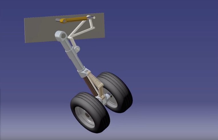
Figure 9 — Four-bar crank-rocker kinematic diagram for aircraft landing gear actuation
The crank-rocker four-bar mechanism converts continuous hydraulic actuator rotation (crank) into controlled oscillatory motion of the landing gear (rocker) through a coupler link, with the aircraft frame serving as the ground link. Grashof’s condition governs mechanism mobility:
S + L ≤ P + Q
where S = shortest link, L = longest link, P and Q = remaining links. Satisfaction of this inequality guarantees that the crank can undergo full rotation, enabling continuous actuator-driven deployment and retraction of the landing gear.
4. Fuselage Structural Analysis — ANSYS Mechanical (FEA)-
Material: Aluminium 7570 · Shell Thickness: 2 mm · Fixed Support: Tail section
4.1 Pressure Loading Cases-
Uniform pressure was applied to the fuselage outer surface at three magnitudes. The following figures present total deformation, von Mises stress, and von Mises strain results for each case.
“The 50 MPa case was included as an extreme-load sensitivity scenario to evaluate structural behaviour beyond nominal operating conditions.”
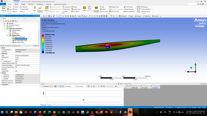
Figure 10 — Total deformation contour at 0.5 MPa internal pressure
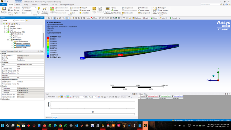
Figure 11 — Von Mises stress distribution at 0.5 MPa

Figure 12 — Von Mises strain at 0.5 MPa
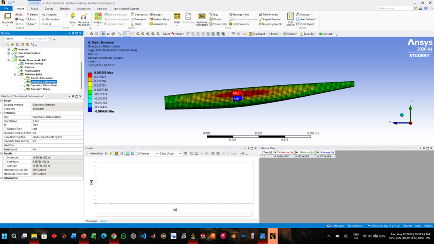
Figure 13 — Total deformation contour at 1.0 MPa internal pressure
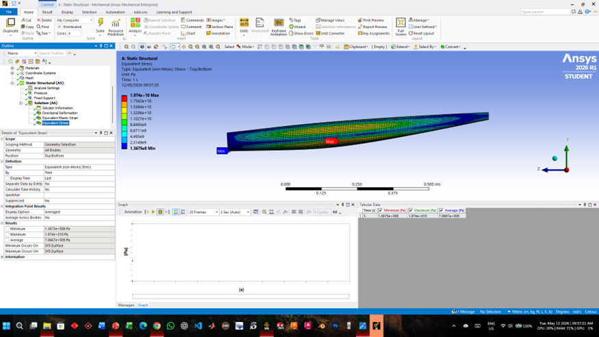
Figure 14 — Von Mises stress distribution at 1.0 MPa
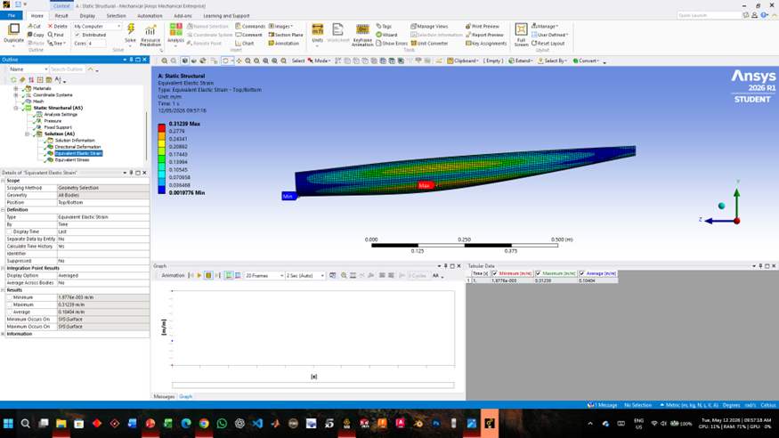
Figure 15 — Von Mises strain at 1.0 MPa
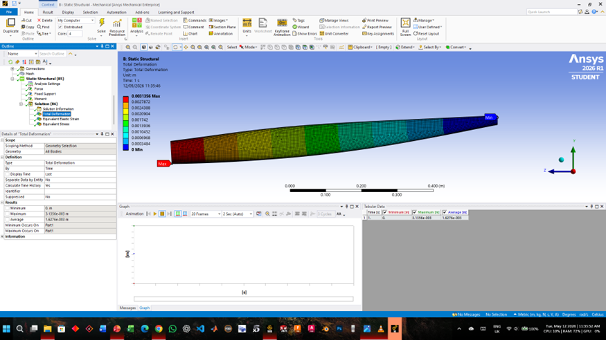
Figure 16 — Total deformation contour at 50 MPa pressure loading

Figure 17 — Von Mises stress distribution at 50 MPa
Pressure Simulation Observations-
- Deformation increases linearly with applied pressure, consistent with linear-elastic material response of Aluminium 7570.
- Maximum stress concentrations are localised at the fixed tail constraint boundary — the primary load transfer point.
- At 50 MPa, strain magnitudes are substantially elevated relative to the 0.5 MPa case, indicating the structural sensitivity to extreme loading.
- Stress distribution patterns remain qualitatively similar across all three pressure cases, with only magnitude varying
4.2 Wing-Root Force & Moment Loading
A face split was created on the fuselage surface at the wing mounting interface. Applied loads: 100 N force and 1 N·m torque — representative of wing aerodynamic load transfer.
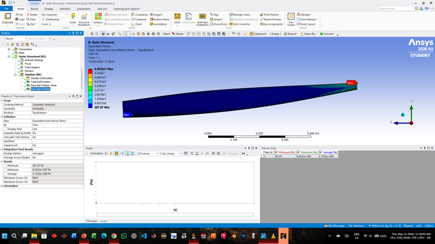
Wing-Root Observations
- Stress concentrations peak at the wing-root face split, clearly identifying the critical load path between wing and fuselage.
- Deformation propagates along the fuselage shell in the direction of the applied force vector.
- The von Mises stress distribution highlights structural regions requiring local reinforcement or geometric blending in detailed design.
Conclusion-
Following successful CFD simulations in ANSYS Fluent and structural FEA in ANSYS Mechanical, the following principal conclusions are drawn:
- The NACA 2412 front wing generated 89.4 N of lift with only 14.4 N of drag at 20 m/s, achieving a lift-to-drag ratio of 6.2 at zero angle of attack. Pressure contours confirmed expected leading-edge stagnation and upper-surface low-pressure regions. The aerofoil is well-suited for front wing applications in subsonic UAV and light aircraft configurations.
- The NACA 0012 tailfin exhibited a lift coefficient of effectively zero (−0.006) and a low drag coefficient of 0.0093 at 44.32 m/s — consistent with the theoretical aerodynamic behaviour of a symmetric aerofoil at zero angle of attack. These results validate the NACA 0012 as an appropriate vertical stabiliser profile, where aerodynamic neutrality is essential for directional stability.
- The crank-rocker four-bar landing gear mechanism satisfies Grashof’s condition, enabling continuous crank rotation and controlled gear actuation. Its compact folding motion, simple actuation, and reliable force transmission make it a mechanically efficient choice for aircraft landing gear systems.
- Fuselage FEA results confirm that deformation and stress scale predictably with applied pressure magnitude. Stress concentrations are consistently highest at the tail constraint and the wing-root interface — regions that represent the primary design-critical zones for structural reinforcement. Aluminium 7570 exhibits acceptable structural response across all simulated load cases.
The combined CFD and FEA analyses provide a validated, multi-disciplinary understanding of the aerodynamic and structural behaviour of key aircraft components. These results serve as a rigorous foundation for further design iteration, material selection studies, and multi-objective optimisation in the detailed design phase.
References-
[1] ANSYS Fluent User’s Guide — ANSYS Inc.
[2] ANSYS Mechanical User’s Guide — ANSYS Inc.
[3] NACA Aerofoil Database — National Advisory Committee for Aeronautics (NACA/NASA)
[4] Anderson, J. D. — Fundamentals of Aerodynamics (6th Ed.), McGraw-Hill Education
[5] Megson, T. H. G. — Aircraft Structures for Engineering Students (6th Ed.), Butterworth-Heinemann
[6] NASA Technical Memorandum Reports on Wing Aerodynamics — NASA Langley Research Center
[7] Standard Aircraft Design References and CFD Methodologies
Report Information
Report Details
Created: May 19, 2026, 10:15 a.m.
Approved by: Ashmita Das [Diode]
Approval date: None
Report Details
Created: May 19, 2026, 10:15 a.m.
Approved by: Ashmita Das [Diode]
Approval date: None