

Design of Robotic Arm
Abstract
Abstract
Gmeet Link : meet.google.com/uuc-rjve-ynn
1. INTRODUCTION
In modern industrial automation, robotic arm manipulators are critical for executing complex, high-precision tasks. Designing these multi-degree-of-freedom (DoF) systems requires a rigorous blend of mechanical design, kinematic modeling, and dynamic simulation. To minimize physical prototyping risks and optimize performance, virtual validation within computational environments has become an industry standard.
1.1 Project Background and Motivation
This project focuses on the design, simulation, and comparative analysis of three distinct robotic arm architectures developed independently by three mentees. Each model represents a unique approach to solving specific manipulation challenges, varying in structural configuration, joint mechanisms, and degrees of freedom.
To evaluate and validate these designs under uniform operational conditions, the project utilizes the MATLAB ecosystem. By leveraging Simulink for control logic and trajectory generation, alongside Simscape Multibody for high-fidelity, 3D rigid-body physics simulation, the project bypasses tedious manual derivation of complex equations of motion while maintaining real-world physical accuracy.
1.2 Project Objectives
- To impart basic knowledge of kinematics, actuators, and mechanical design in robotics.
- To simulate a compact robotic arm with multiple degrees of freedom using MATLAB.
- To validate mathematical models through Simscape Multibody.
- To provide a roadmap for hardware fabrication and advanced control implementation.
1.3 Report Structure
This report details the literature review, mechanical design using Onshape, kinematic analysis via MATLAB, and the final results from simulation validation.
Section 2 - Mechanical Design and Technical Specifications
Section 3 - Kinematic Analyses and Models
Section 4 - Results and Conclusion
2. MECHANICAL DESIGN AND TECHNICAL SPECIFICATIONS
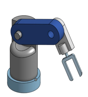
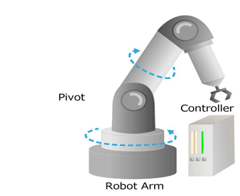
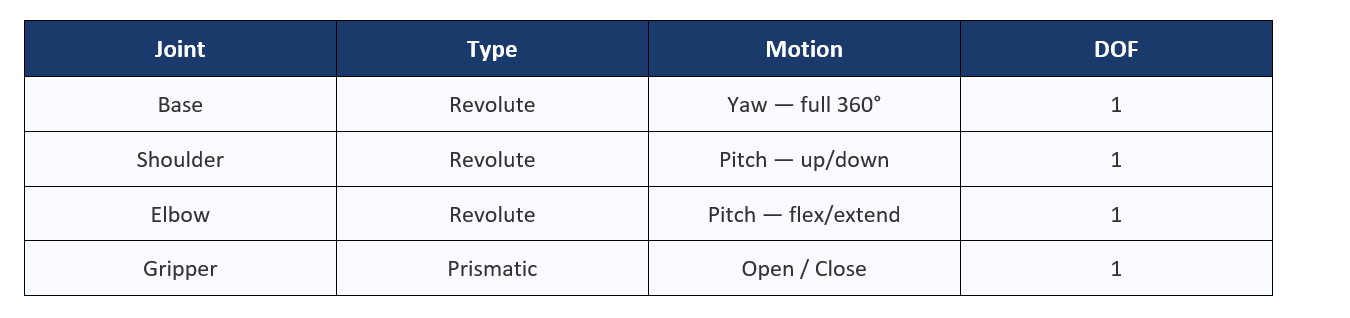
2.1 Manipulator Configuration
The manipulators are articulated arms with 3 to 4 Degrees of Freedom designed for versatile task execution.
2.2 CAD Development
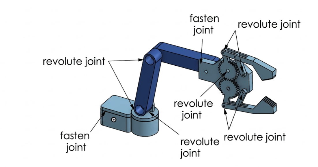
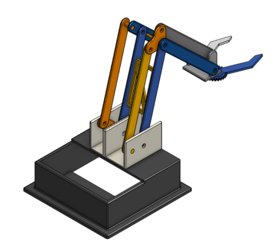
Components, including the base, links, and joints, were modelled in Onshape. Assembly constraints were applied to ensure a proper range of motion for each DOF. Primarily, the revolute joint and the fasten joint were used.
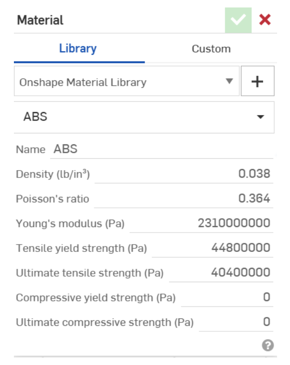
2.3 Mass and Inertial Properties
Physical properties such as the centre of mass and material density were assigned to ensure realistic behaviour in the physics engine. All the parts of the object were made of ABS (Acrylonitrile Butadiene Styrene), a common 3D printing material.
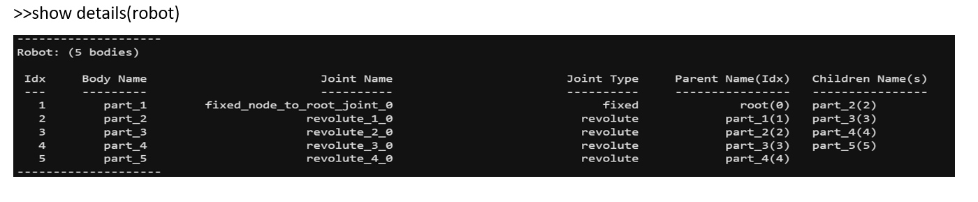
2.4 URDF Generation
The assembly was exported as a Unified Robot Description Format (URDF) file and an Extensible Markup Language (XML) file, enabling seamless transfer of the mechanical model into MATLAB.
3. Kinematic Analysis (MATLAB Simulink & Simscape)
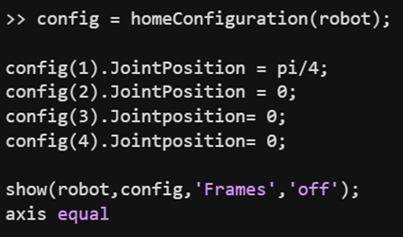
3.1 Forward Kinematics
Forward kinematics was implemented using two distinct methods: direct mathematical computation in MATLAB and a physics-based simulation in Simscape Multibody.
MATLAB Implementation
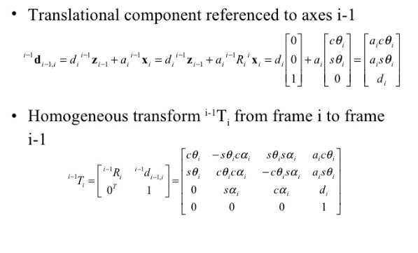
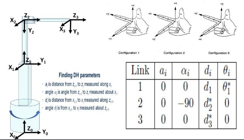
This method calculates the pose using successive homogeneous transformation matrices derived from the Denavit-Hartenberg (DH) table.
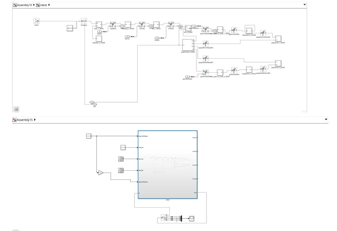
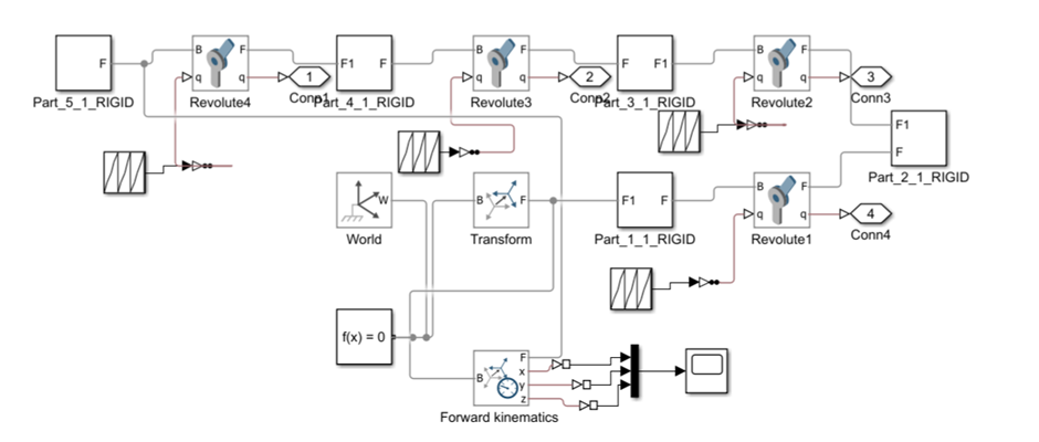
Simscape Multibody Implementation
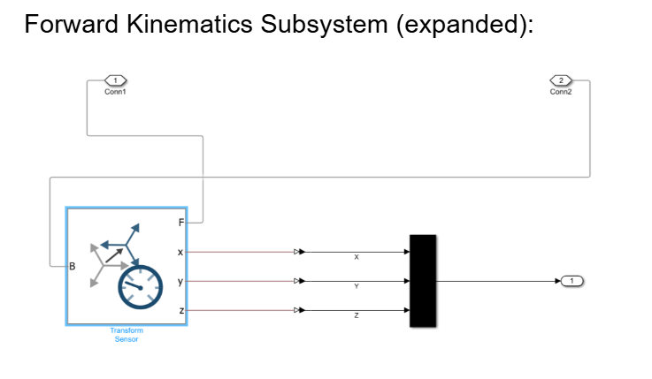
This approach uses a rigid body model in which the pose is read directly from Frame Sensors mounted on the end-effector and the base. This dual-method approach ensures the mathematical model is validated against a physics-based simulation.
3.2 Inverse Kinematics
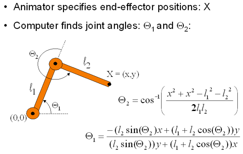
Inverse kinematics (IK) is a mathematical and computational process used in robotics and animation to determine the required joint parameters (such as angles or lengths) to position the end of a chain—such as a robotic gripper or an animated character's hand—at a specific target position and orientation.
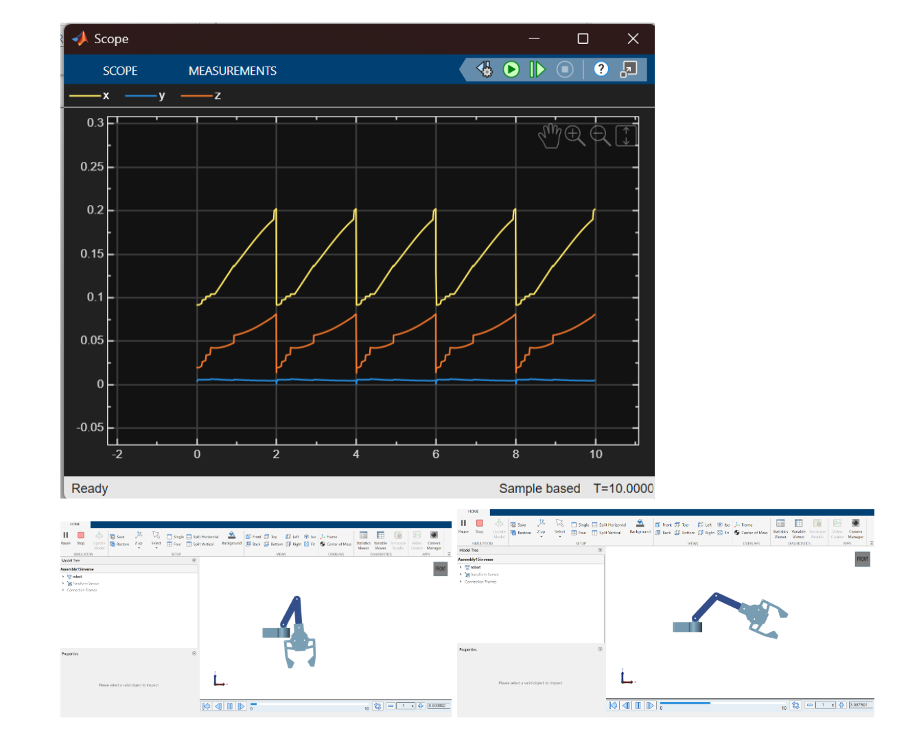
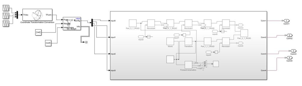
Inverse kinematics was implemented in the Simscape Multibody environment using the inverse kinematics block.
MODEL 1 - ANIRUDH JAYAN
MODEL AND SPECIFICATIONS
MATLAB IMPLEMENTATION
FORWARD KINEMATICS
INVERSE KINEMATICS

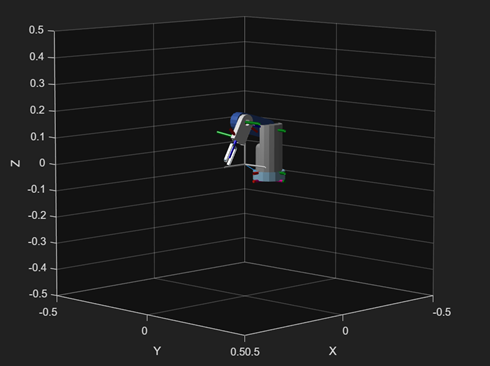
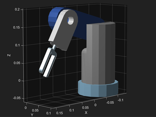
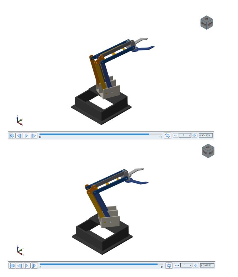
MODEL 2 - NAISHA DHAWALE
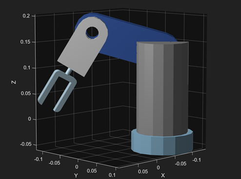
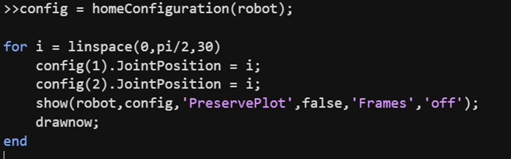
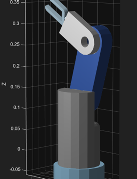
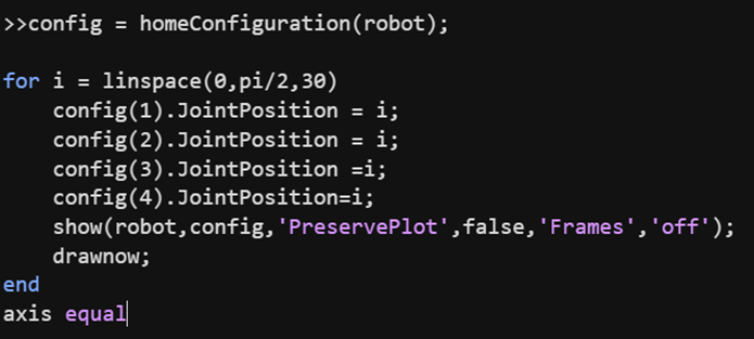
MODEL AND SPECIFICATIONS
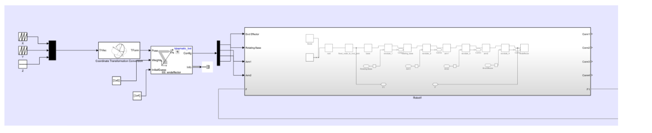
MATLAB SIMULATION
![]()
![]()
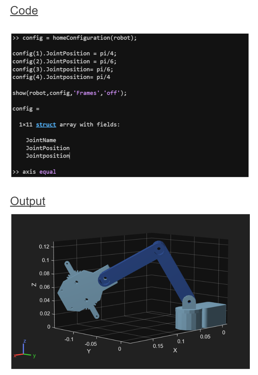
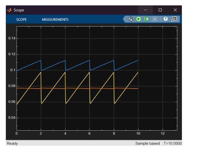
FORWARD KINEMATICS
INVERSE KINEMATICS
MODEL 3 - GRACESON RAJ
MODEL AND SPECIFICATIONS
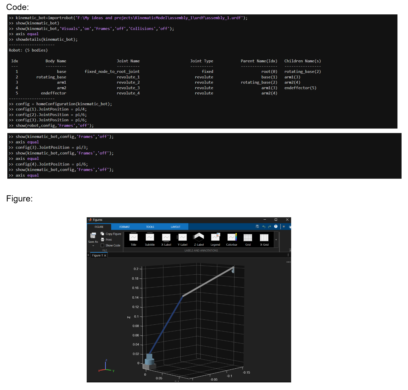
FORWARD KINEMATICS IN MATLAB
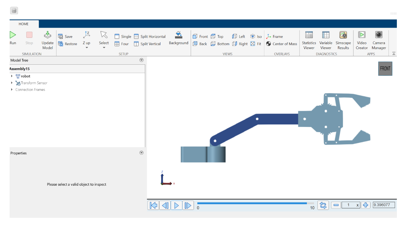
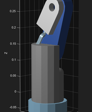
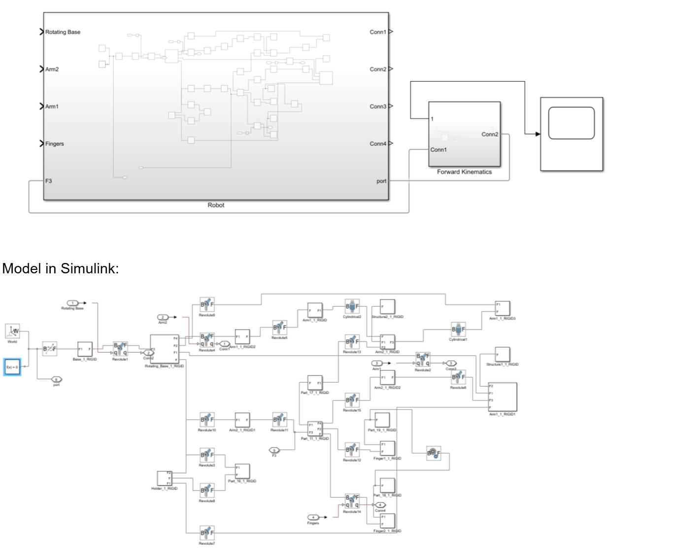
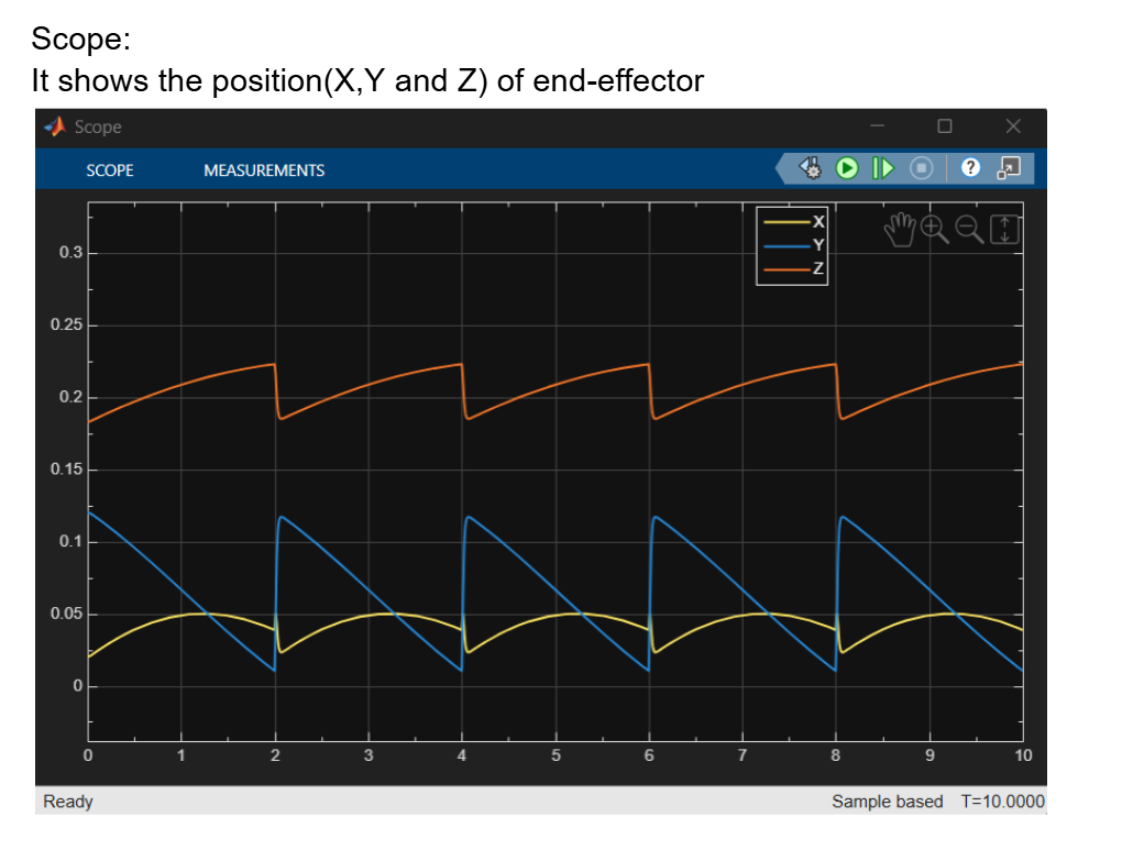
FORWARD KINEMATICS IN SIMSCAPE
INVERSE KINEMATICS IN SIMSCAPE
4. Results and Conclusion
1. Kinematic Accuracy
The arm successfully reached target coordinates within the defined tolerance.
2. Trajectory Execution
Simulation results demonstrated smooth joint velocity profiles and manageable torque requirements, confirming the mechanical design's validity.
3. System Performance
Challenges such as control loop latency and singularity regions were identified and resolved by adjusting solver parameters and implementing damping in the IK algorithms.
Report Information
Report Details
Created: May 19, 2026, 1:05 a.m.
Approved by: None
Approval date: None
Report Details
Created: May 19, 2026, 1:05 a.m.
Approved by: None
Approval date: None