

ROUV: Remotely Operated Underwater Vehicle
Abstract
Abstract
Introduction
For conducting effective research in underwater ecosystems without human intervention, an Underwater Vehicle (UV) is essential. This project aims to design and develop a 2-DOF UV capable of precise navigation by tracking underwater objects. Movements are controlled using bilge pumps and propellers. It is manually controlled using a remote.
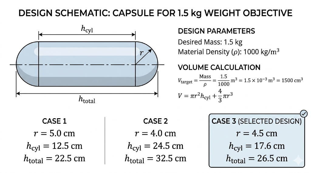
Understanding the Design
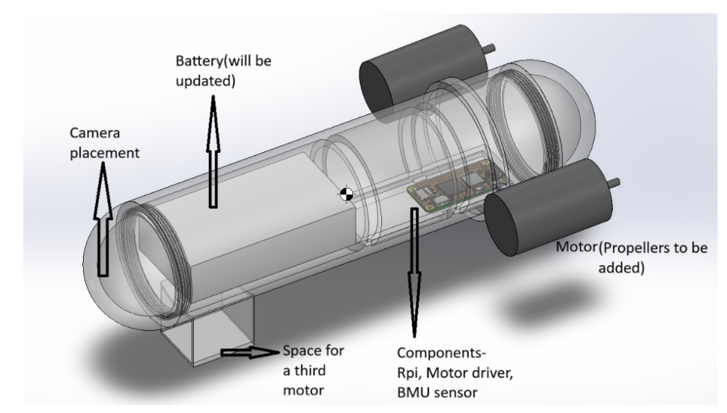
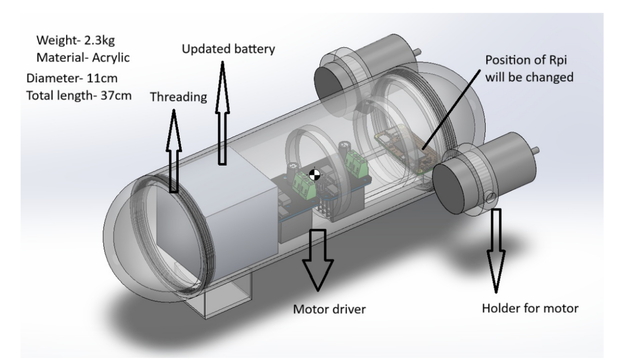
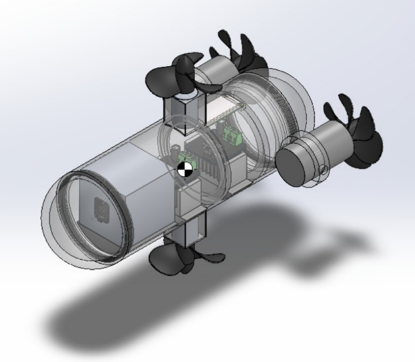
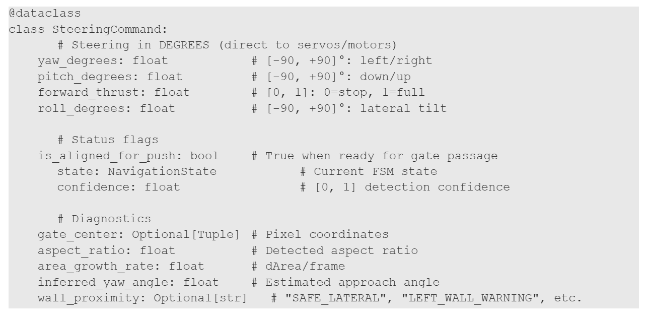
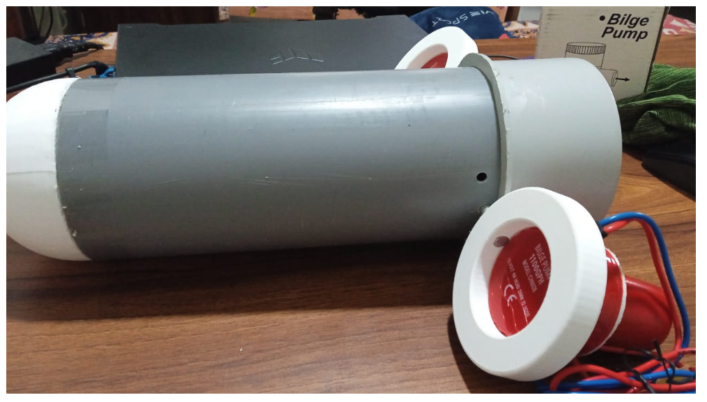
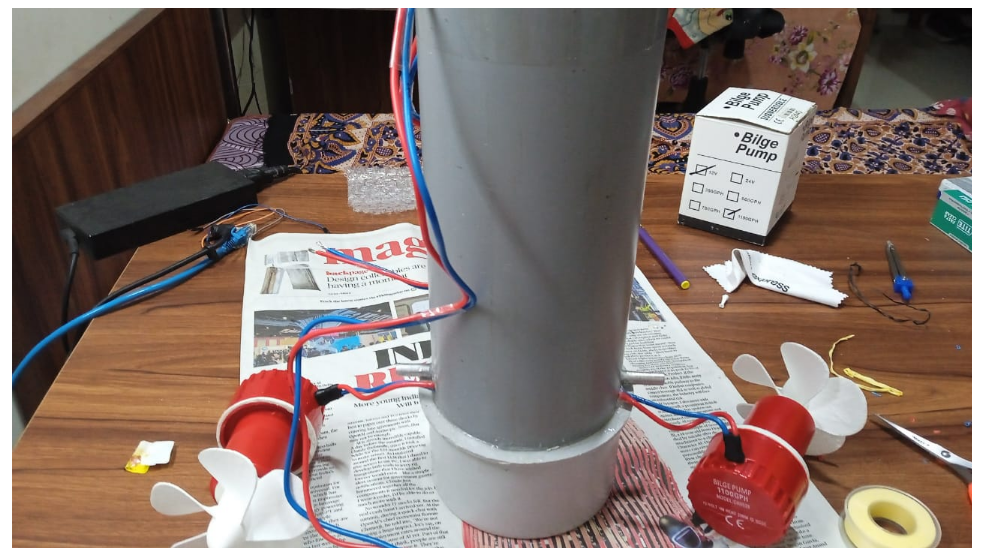
We have chosen a cylindrical body with spherical ends because it is aerodynamically efficient (reduces drag) and is generally used in submarines. To make it waterproof at the ends and for easy assembly and disassembly, we have provided threading on both sides. We have placed the motors at the end (for surge) as the battery is in the front, and the weight will be balanced. First, we planned to keep only one motor at the bottom (which we later changed) for the heave motion.
Design Analysis Using Ansys
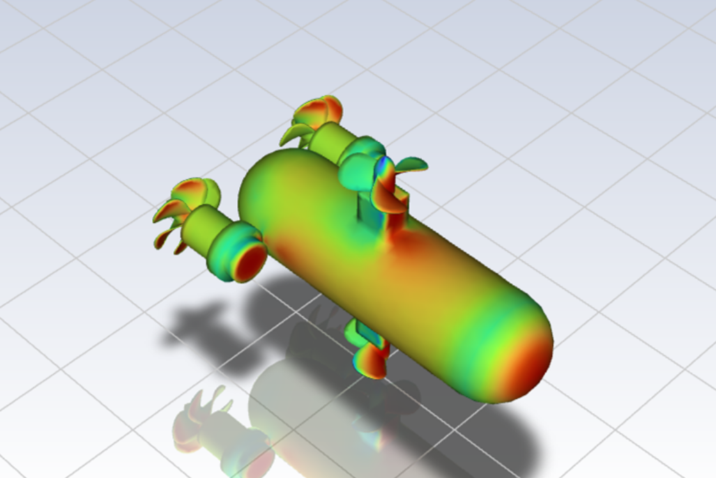
As shown in Fig. 6 and 7 from the Ansys analysis, the wake is stable. A stable wake is the region of disturbed flow behind a moving object (such as an aeroplane, ship, or wind turbine) that maintains a predictable, steady pattern rather than breaking down into chaotic turbulence.
Velocity of UV = 0.7 m/s
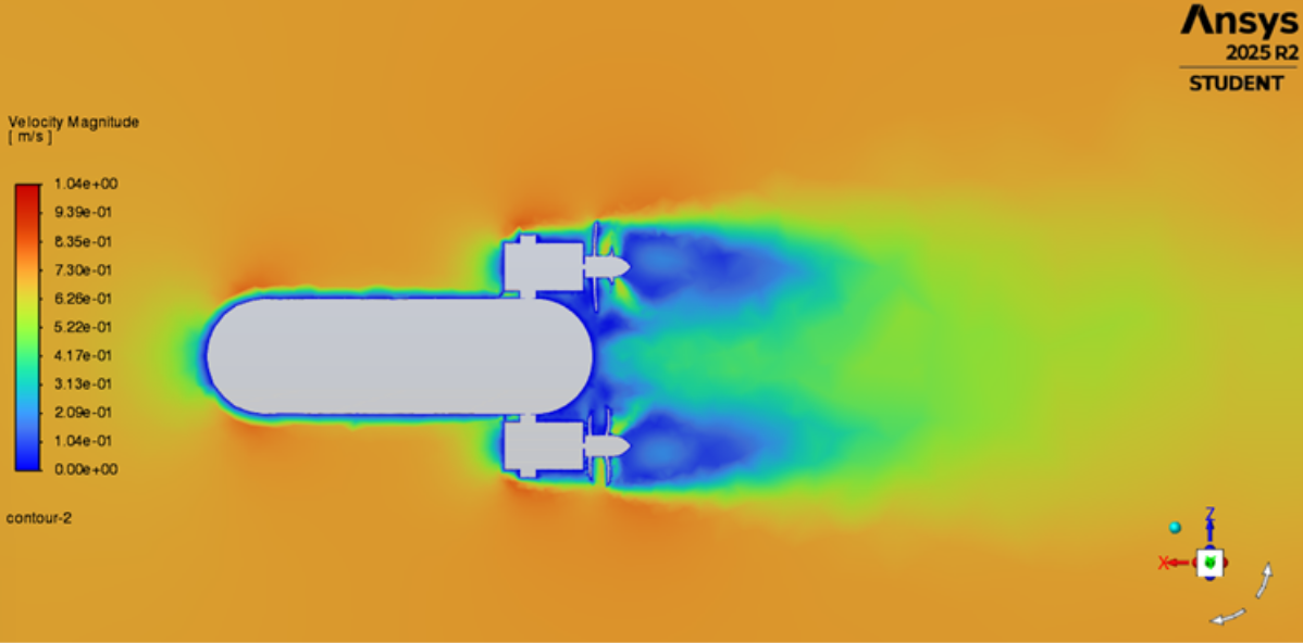
The blue-purple blobs behind the thrusters and the main body represent low-velocity zones where energy is being lost.
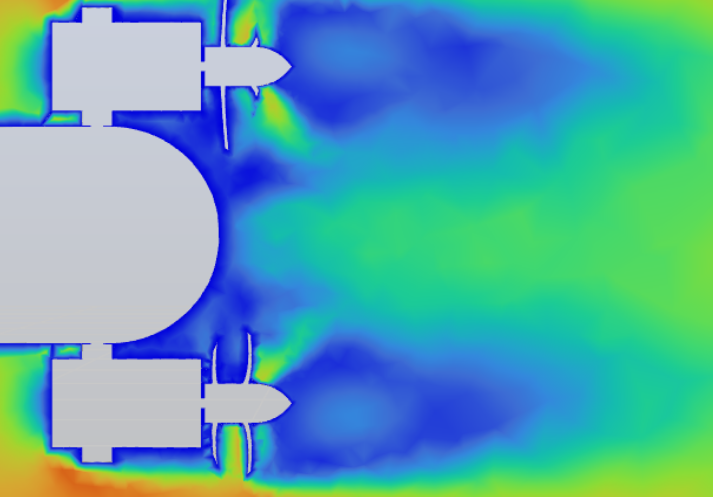
Another side view is seen in Fig. 8 - There is significant drag (loss of velocity) near the top and bottom thrusters as well.
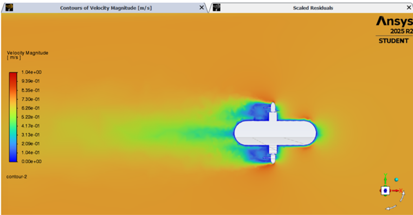
Static Pressure analysis: Pressure is highest at points where the fluid abruptly comes to a stop.
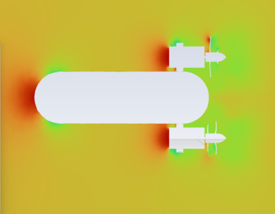
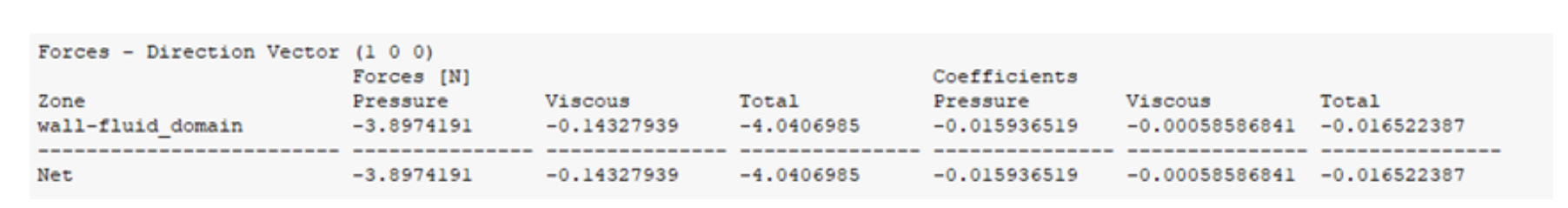
As calculated, the total drag force is 4.04N, and the thruster's velocity should match that of 4.04N for the AUV to run at 0.7m/s.
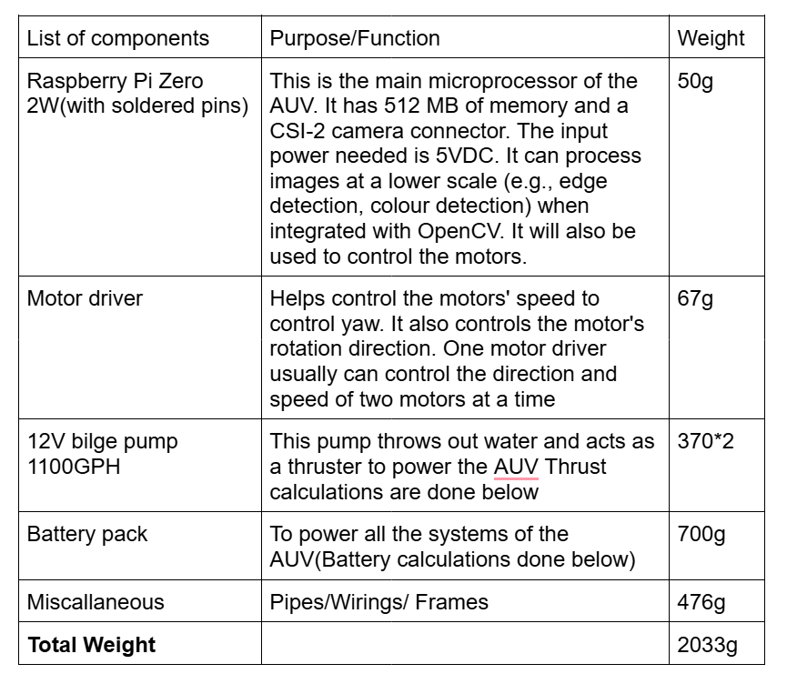
Electronics Components
Calculations
- Thrust Calculations:
Flow rate 1100GPH per pump: 1100*3.785 = 4163.5
L/hour = 1.1565L/s=0.00156m3/s
Mass flow rate per pump= Density*Volume flow rate = 1.56kg/s
Outlet flow velocity of bilge pump= 1.5m/s
Thrust provided per pump= mass flow rate*velocity= 1.56*1.5= 2.34N
Assuming a loss of 60% due to various backflows, swirls, etc.
Real thrust provided by the pumps = 1N*2
Total thrust provided = 2N
- Velocity of AUV calculation:
T= F(drag)
Taking Cd= 0.5
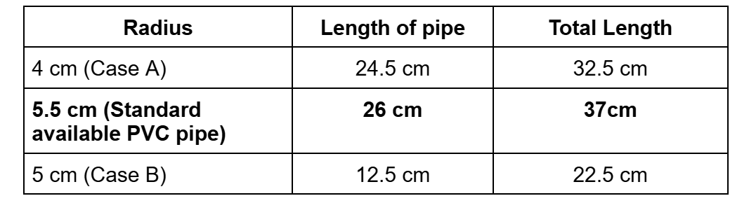
Frontal Area = 0.00785 m2 (Case A)
Frontal Area = 0.05026 m2 (Case B)
Velocity we can reach= 1m/s (Case A)
Velocity we can reach= 1.26 m/s (Case B)
With a larger weight (3.5 kg~4 kg), we can approximately reach 0.5 m/s.
- Battery requirements:
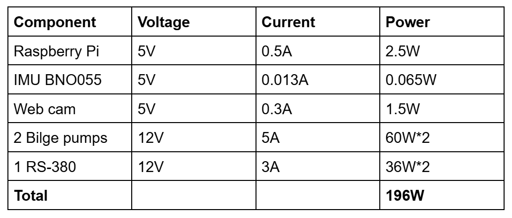
Table: Battery Requirements
Battery current required= 196W/12V= 16.33A
Battery runtime = 20 minutes
Battery capacity=16.33/3= 5.44Ah
Battery: https://robu.in/product/pro-range-ifr-32650-12-8v-6000mah-3c-4s1p-lifepo4-battery-pack/ This battery would perform fairly well. The conditions considered are the peak operating conditions, and the actual values may be less.
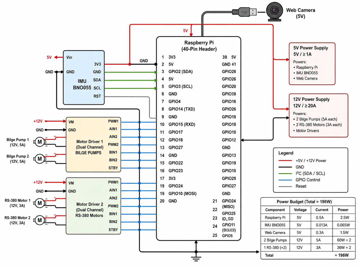
Connection Diagram:
Vision System for Autonomous Gate Navigation
Overview and Problem Statement: While the mechanical design and electronics provide the AUV with thrust and control, autonomous mission capability requires computer vision for gate detection and navigation. The challenge is that gates are fixed at arbitrary depths and orientations in the 50m × 25m pool, requiring the AUV to approach each gate perpendicular to within a strict tolerance of less than 5 degrees yaw angle — all using camera input with no external sensors.
System Specifications: The vision system is optimized for the following operating environment:
- Pool dimensions: 50m × 25m with variable depth
- Gate specifications: 0.5m × 0.5m hollow PVC squares, vertically oriented
- Distance between gates: 10 meters
- Camera: 90° field of view, 320×240 resolution (optimized for embedded processing)
- Processing platform: Raspberry Pi Zero 2W
- Required gate detection rate: >95%
- Required alignment success rate: >90%
- Required approach tolerance: <5° yaw from head-on
- Target frame rate: ≥15 FPS (achieved: 18–22 FPS)
Technical Approach:
Perspective Compensation via Aspect Ratio:
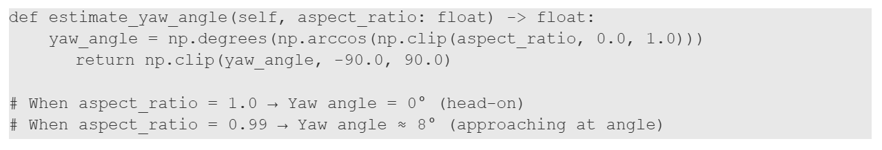
The fundamental innovation in this vision system is the use of aspect ratio (width/height) to infer the approach angle. A square gate viewed head-on has an aspect ratio of approximately 1.0. When viewed from a 30-degree angle, the same gate has an aspect ratio of approximately 0.65 due to perspective compression.
Mapping of aspect ratio to yaw angle: (Aspect Ratio - Inferred Yaw Angle)
- 1.000 - 0° (head-on)
- 0.999 ≈ 2.6° (well-aligned)
- 0.995 ≈ 5.7° (acceptable)
- 0.990 ≈ 8° (improving alignment)
- 0.980 ≈ 11° (approaching at angle)
Vision Processing Pipeline:
The system processes every camera frame through a six-stage pipeline optimized for underwater robustness:
- Stage 1 — Grayscale Conversion: Raw RGB frames are converted to grayscale, discarding color information which is unreliable underwater due to varying water absorption.
- Stage 2 — CLAHE (Underwater Contrast Enhancement): Contrast Limited Adaptive Histogram Equalization compensates for uneven underwater lighting. This step is critical for consistent edge detection across varying illumination conditions.
- Stage 3 — Gaussian Blur: A 5×5 Gaussian kernel smooths the image to reduce noise while preserving real edges.
- Stage 4 — Canny Edge Detection: Applies two tunable thresholds (default: min=50, max=150) to detect edges. These thresholds are accessible via trackbars in the testing interface for real-time tuning.
- Stage 5 — Contour Finding: OpenCV's contour finder locates all closed shapes in the edge map. The system filters strictly for exactly 4 vertices, rejecting triangles, pentagons, and noise.
- Stage 6 — Gate Candidate Scoring: Multiple 4-sided contours are scored by area (40% weight), aspect ratio (30%), wall safety (20%), and regularity (10%). The highest-scoring candidate becomes the navigation target.
Alignment Criteria and Strict Yaw Tolerance:
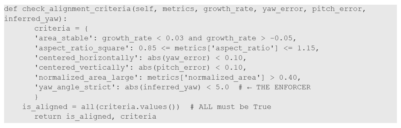
The system enforces six simultaneous alignment criteria, all of which must be true before the AUV is cleared to pass through a gate:
- Area Stable — Gate area must grow <3% per frame (optimal approach)
- Aspect Ratio Square — 0.85–1.15 range (head-on view)
- Centered Horizontally — Yaw error <±5% of frame width
- Centered Vertically — Pitch error <±5% of frame height
- Large Enough — Normalized area >0.40 (gate visible and close enough)
- Yaw Angle Strict — Inferred yaw <5.0° (HARD CONSTRAINT; non-negotiable)
All six criteria are continuously monitored during the APPROACH state. The system only transitions to ALIGNED when all six are simultaneously true, ensuring the AUV cannot attempt passage at angles that would cause clipping or deflection.
Navigation State Machine:
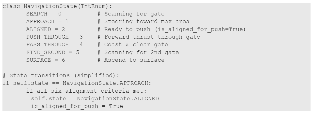
The system orchestrates multi-gate navigation through six sequential states with automatic transitions:
- SEARCH: Scans for any valid gate candidate. Output: zero steering, no thrust.
- APPROACH: Gate detected; computes steering errors and applies thrust. Forward thrust is enabled if the area is growing and the gate is large enough.
- ALIGNED: All six criteria met; gate is head-on and centred. Flag is_aligned_for_push is set to TRUE.
- PUSH_THROUGH: Forward thrust at maximum (1.0), yaw/pitch held from ALIGNED state.
- PASS_THROUGH: Gate exiting view; coasts forward at light thrust (0.3) for 2 seconds to ensure clearance.
- FIND_SECOND / SURFACE: Resume scanning for the second gate, or ascend to the surface after both gates are passed.
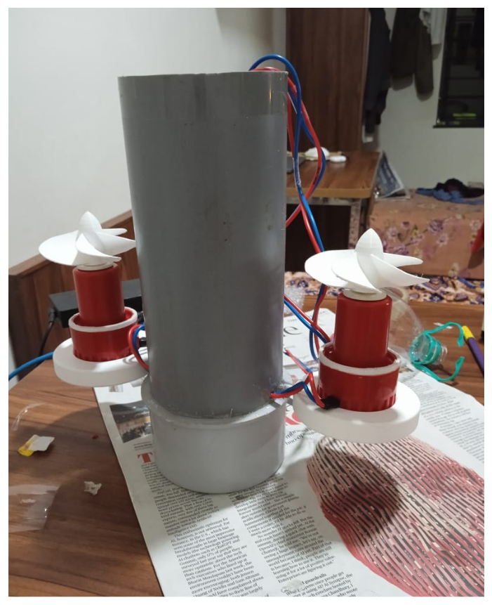
Steering Command Output:
Every frame produces a SteeringCommand object with the following degree-based outputs:
- yaw_degrees [−90, +90]: Negative = turn left, Positive = turn right
- pitch_degrees [−90, +90]: Negative = pitch down, Positive = pitch up
- forward_thrust [0, 1]: 0 = stop, 1.0 = full speed
- is_aligned_for_push (bool): TRUE when all 6 criteria met; signals gate passage ready
- state: Current FSM state (SEARCH, APPROACH, ALIGNED, PUSH_THROUGH, etc.)
- confidence [0, 1]: Detection confidence
Key Innovations:
- Aspect Ratio as Angle Inference — Novel use of geometric distortion to infer 3D approach angle from 2D camera projection.
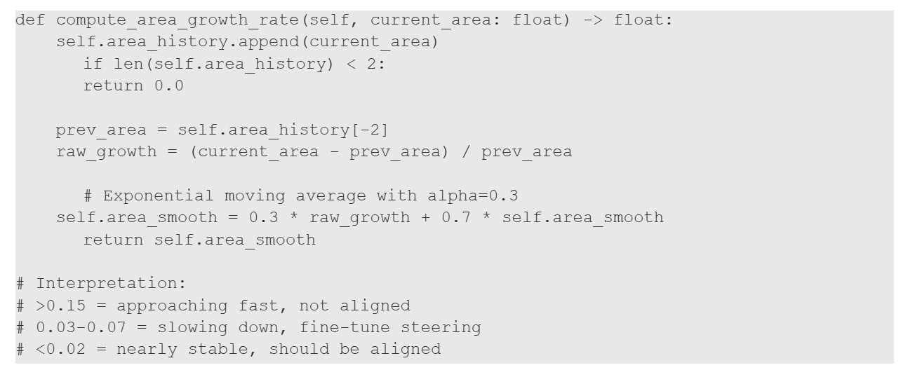
- Area-Maximization Steering — Growth rate tracking guides optimal head-on approach using only frame-relative measurements.
- Six-Point Multidimensional Alignment — Robust safety check from six independent metrics, preventing false positives.
- Vision-Only Wall Avoidance — Proximity inference from camera frame geometry alone, eliminating the need for external sensors.
- Degree-Based Output Architecture — Direct servo/motor integration without normalisation layers.
Code Implementation at Critical Sections:
Snapshot 1: Aspect Ratio to Yaw Angle Conversion - This is the core innovation, where the arccos function maps aspect ratio directly to the approach angle.
Snapshot 2: Six-Point Alignment Check (MOST CRITICAL) - ALL six must be True for is_aligned_for_push = True. Criterion 6 enforces strict <5° yaw tolerance.
Snapshot 3: Area Growth Rate Tracking - Tracks how fast the gate area is growing—indicates optimal approach when growth drops below 3%.
Snapshot 4: State Machine Core - Six-state orchestration for autonomous multi-gate navigation.
Snapshot 5: Steering Command Output Structure - Degree-based steering output for direct servo/motor control.
Summary of Vision System Implementation :
The vision system achieves autonomous multi-gate navigation through:
- Perspective compensation (aspect ratio → yaw angle inference)
- Six-stage image processing pipeline (Grayscale → CLAHE → Blur → Canny → Contours)
- Strict validation criteria (4 vertices, hollow frame, nearly square geometry)
- Weighted scoring function (area, aspect, safety, regularity)
- Six simultaneous alignment criteria with <5° yaw enforcement
- Area-maximisation steering (growth rate tracking)
- Six-state finite state machine (SEARCH → SURFACE)
- Degree-based steering output (direct servo/motor control)
- Vision-only wall avoidance (frame geometry inference)
- Real-time performance (18-22 FPS on Raspberry Pi Zero 2W)
This integrated system enables the AUV to autonomously navigate through multiple suspended gates at arbitrary depths with strict approach precision, wall safety, and production-ready reliability.
Images of the ROUV - Fabrication
Documentation
Extended documentation of the project can be found below:
- CAD Files, Simulations and Testing: https://drive.google.com/drive/folders/1c457ursU3BPC1jdq1-e0OfBxJ4OgN0ON
- GitHub Repository: https://github.com/Tej36asvi/AUV-Navigation-and-Vision-pipeline
The Team
Mentors
- Debarghya Banerjee [Piston]
- Shubhang S. Galagali [Piston]
- Rishit Prakash [Psiton]
- Anagha Hatwar K. R. [Diode]
Mentees
- Shreyas Kodancha [Piston]
- Tejasvi Karanth [Piston]
- R. Sri Harihara Moorthy [Piston]
Report Information
Team Members
Team Members
Report Details
Created: April 8, 2026, 4:49 p.m.
Approved by: None
Approval date: None
Report Details
Created: April 8, 2026, 4:49 p.m.
Approved by: None
Approval date: None