

Hardware_Ping_Pong_RTL
Abstract
Abstract
Abstract:
This project presents an FPGA-based implementation of both two player and CPU mode Ping Pong Game using Verilog HDL. The objective is to showcase the capabilities of FPGA platforms in real-time, interactive digital environments. The game logic comprising ball kinematics, paddle movement, collision physics, and dynamic score tracking is implemented entirely through synchronous logic , finite state machines (FSMs) and peripheral interfacing. The game is displayed on a VGA-compatible monitor, interfaced with the FPGA. The project serves as a practical exploration of hardware-software integration, digital design principles, and real-time embedded systems, making it an engaging demonstration of FPGA-based gaming applications.
Introduction:
Pong is one of the earliest and most iconic arcade games, challenging two players to control paddles and rally a ball across the screen without letting it pass their side. Originally introduced in 1972 by Atari, it laid the foundation for the entire video game industry and remains a timeless example of simple yet engaging real-time gameplay.
This project implements the Pong Game on the Nexys4 Artix 7 DDR FPGA board using Verilog HDL, displaying it on a VGA compatible monitor. Unlike software-based implementations that rely on microcontrollers or processors, this version of the game is entirely hardware-driven. The FPGA directly handles user input, game logic, collision detection, and VGA output generation. This approach ensures low-latency gameplay and serves as a hands-on demonstration of FPGA capabilities in real-time digital systems.
To elevate the classic mechanics, this version includes several advanced features: a "Noob Switch" that toggles between slow-motion for demonstrations and high-speed for competition, a CPU mode with both beatable and "unbeatable" difficulty levels, and a Power-Up system that dynamically doubles paddle size for seven seconds. These elements require precise timing control and memory handling to maintain a seamless user experience across the Welcome and End screens.
Methodology:
Description of the Game
Pong is a classic arcade-style game where two players control paddles on opposite sides of a rectangular play field. The objective is to deflect a continuously moving ball past the opponent's paddle, scoring a point each time the ball crosses their boundary. The game becomes progressively more intense as the ball speed varies depending on where it strikes the paddle, requiring precise positioning and quick reactions to outplay the opponent. The first player to reach three points wins the game.
The paddle movement is controlled in two directions up and down using external input buttons on the FPGA board. Each player controls their respective paddle independently, and the paddle moves continuously in the chosen direction as long as the button is held. The movement follows a fixed update rate dictated by a clock signal, ensuring smooth and consistent gameplay experience. The game also features a CPU mode, where Player 1's paddle is replaced by an CPU opponent that automatically tracks the ball's position, providing a single-player experience. The ball's movement is governed by continuous horizontal and vertical velocity components, with its direction reversing upon contact with the top and bottom borders or either player's paddle. When the ball strikes a paddle, the speed is adjusted based on the region of contact hitting the edges of the paddle results in a faster ball, while hitting the center results in a slower one, adding a strategic element to paddle positioning.
To add unpredictable gameplay, the project uses a Linear Feedback Shift Register (LFSR) as a hardware-based pseudorandom generator. By sampling the LFSR's bit patterns at the moment of a side-wall collision, the system assigns a new random velocity to the ball, ensuring every round follows a unique path. Additionally, the LFSR dictates the randomized timing and coordinates for power-up spawns, such as the paddle-doubling bonus. This hardware-driven randomness prevents repetitive patterns and transforms the classic simulation into a dynamic, competitive experience.
Implementation:
The Pong game is implemented in Verilog HDL on a Nexys 4 DDR FPGA, using a six-state FSM (START,RESET,WAIT,IDLE, PLAY, MISS) to manage game flow and scoring. Ball physics and paddle interactions are handled via registers, featuring a five-zone segmented paddle system that dynamically adjusts ball speed between 5 and 11 pixels per frame. To ensure fluid gameplay, a custom VGA controller generates 640×480 synchronization signals at 60Hz, using look-ahead logic for collision detection to prevent "tunneling" at high speeds.
Beyond core mechanics, the system integrates advanced hardware features including an CPU opponent with dual difficulty levels and a power-up system that doubles paddle height. A Linear Feedback Shift Register (LFSR) ensures randomized serves. All elements from the dotted center line to the score digits are rendered in real-time through a priority-based combinational display block synchronized to the onboard 100MHz oscillator.
Hardware:
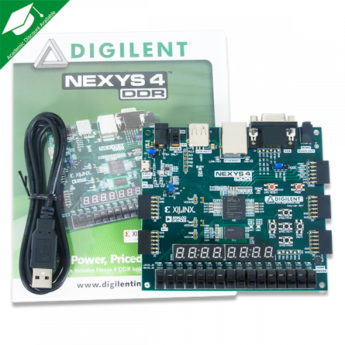
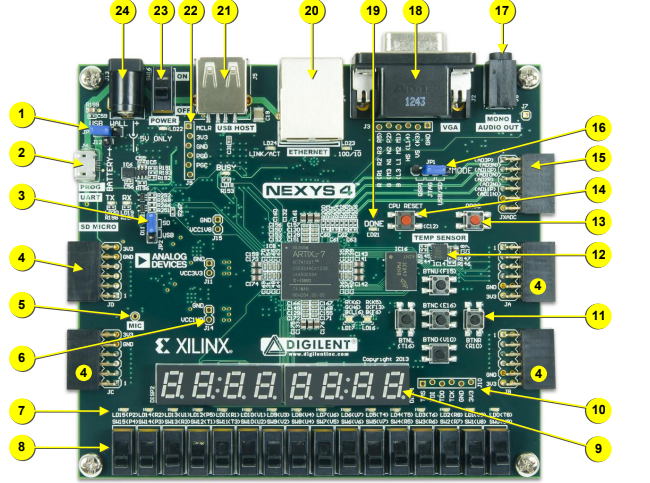
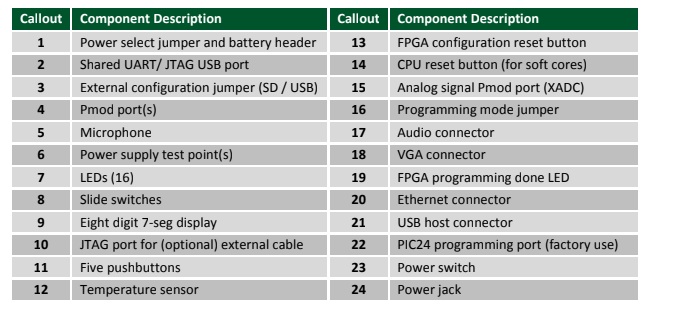
The system is implemented on a Nexys4 Artix 7 DDR FPGA board. The Nexys 4 board is a complete, ready-to-use digital circuit development platform based on the latest Artix-7TM Field Programmable Gate Array (FPGA) from Xilinx. With its large, high-capacity FPGA (Xilinx part number XC7A100TCSG324), generous external memories, and collection of USB, Ethernet, and other ports, the Nexys 4 can host designs ranging from introductory combinational circuits to powerful embedded processors. Several built-in peripherals, including an accelerometer, temperature sensor, MEMs digital microphone, a speaker amplifier, and a lot of I/O devices allow the Nexys 4 to be used for a wide range of designs without needing any other components. The Nexys 4 FPGA board includes the following ports and peripherals:
• User Interface & Display:
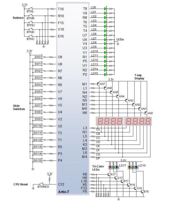
– 16 user switches
– 16 user LEDs
– Two 4-digit 7-segment displays
– Two tri-color LEDs
• Communication & Storage:
– USB-UART Bridge
– Micro SD card connector
– Serial Flash
– 16Mbyte CellularRAM
– Digilent USB-JTAG port for FPGA programming and communication
– USB HID Host for mice, keyboards, and memory sticks
• Graphics & Audio:
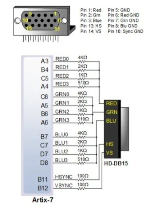
– 12-bit VGA output
– PWM audio output
– PDM microphone
• Sensors & Connectivity:
– 3-axis accelerometer
– Temperature sensor
– 10/100 Ethernet PHY
• Expansion & Interfacing:
– Four Pmod ports
– Pmod for XADC signals
Verilog HDL Hardware:
top_fsmpaddleswithball.v
The pong_game_top module is the top-level module that controls the Pong game on an FPGA, integrating various subsystems such as VGA display, score display, ball and paddle physics, powerup management, and AI opponent control. It interfaces with several components including VGA signals, seven-segment displays for score visualization, and paddle input controls.
The module has input ports for directional button controls (pad1[1:0], pad2[1:0]), mode selection switches (noob_switch, cpu_switch, boss_cpu), clock and reset signals, and output ports for VGA color signals (vga_r, vga_g, vga_b), synchronization signals (hsync, vsync), and seven-segment display signals (ssd_digit, ssd_an).
This module instantiates several specialized submodules to manage the system's complexity. A VGA controller handles pixel scanning and synchronization, while the random_generator_dx_dy and random_generator_power_ups modules utilize 8-bit and 20-bit LFSRs respectively to generate unpredictable ball directions and item spawn coordinates. Timing is regulated by a suite of clock dividers (120Hz, 60Hz, and 500Hz) that drive paddle movement, ball physics, and the sevenseg_score module, which multiplexes player scores across the hardware display.
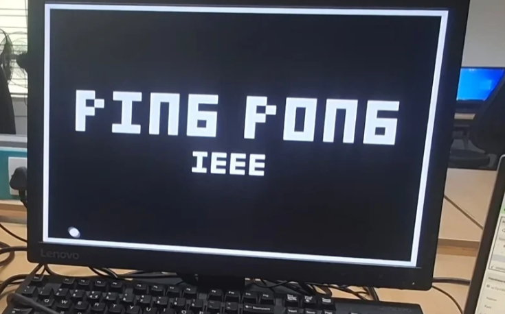
The game mechanics are governed by a six-state FSM comprising START, RESET, WAIT, IDLE, PLAY, and MISS states. START state displays the welcome screen. The RESET state is used to reset the game and start a new game. It basically resets the score and set the paddles and ball to its default lengths and position. The WAIT state is to just ensure that the state directly doesn’t go to PLAY, so it basically waits until no button is pressed and proceed further to IDLE state if no button is pressed. In the IDLE state, the ball remains stationary at the screen center awaiting a button press to begin the rally. Upon transition to PLAY, a random serve direction is latched from the LFSR output and the ball begins moving. Ball position is tracked using signed 10-bit registers ball_x and ball_y representing the horizontal and vertical center coordinates, with movement computed each 60Hz cycle as ball_x + ball_speed and ball_y + ball_speed. Collision detection uses look-ahead position wires ball_x and ball_y to predict the ball's next position before committing the update, preventing tunneling at higher speeds. When the ball misses a paddle and reaches a side wall, the FSM transitions to MISS it displays the end screen if someone wins or else it directs to the WAIT state to continue the current game.
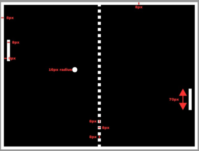
The paddle physics system uses a five-zone segmented contact model where the ball speed varies between 5 and 8 pixels per frame depending on which vertical region of the paddle face the ball contacts. Edge zones produce the highest speed while the center zone produces the slowest, rewarding precise positioning. Paddle positions pad_1_x, pad_1_y and pad_2_x, pad_2_y represent top left corners of the left and right paddles respectively, with boundaries derived as pad_1_y + pad_1_height and pad_2_y + pad_2_height. Variable paddle height registers pad_1_height and p_2_height support the powerup system where paddle height doubles from 70 to 140 pixels for 420 cycles upon powerup collection. Paddle motion uses combinational velocity wires with integrated boundary clamping, ensuring the paddle never exits the playfield regardless of speed or size.
The CPU opponent mode, activated by the cpu_switch switch, replaces left paddle manual control with two selectable difficulty levels governed by the boss_cpu switch. The beatable CPU reacts only when the ball is within 200 pixels of the left paddle and moves at the current ball speed, allowing skilled players to outmaneuver it with sharp angled shots. The unbeatable CPU reacts from halfway across the court and moves at ball speed plus four pixels per frame, guaranteeing it always intercepts the ball. Both modes include a center-drift behavior when the ball is moving away, making the CPU mode appear more natural. The powerup system awards paddle size increase to the player whose side the ball is moving toward at the moment of powerup collection, adding a strategic element to rally positioning. Game termination occurs when either player reaches three points, the game over screen is displayed, with scores and winner identity rendered directly in pixel coordinates using a block-letter font within the combinational display logic.
clock_divider.v
The clock divider modules are used to generate multiple lower-frequency clocks from the FPGA’s 100 MHz system clock to ensure proper timing and synchronization of different subsystems in the Pong game. Since various components operate optimally at different speeds, dedicated clock signals are derived using counter-based frequency division.
A 25 MHz clock is generated for the VGA controller to meet standard display timing requirements, ensuring stable and flicker-free video output. A 120 Hz clock is used for random power-up generation, providing sufficiently fast updates while maintaining controlled spawning behavior. A 60 Hz clock drives the ball and paddle movement, closely matching typical screen refresh rates to achieve smooth and realistic gameplay dynamics. Additionally, a 500 Hz clock is used for multiplexing the seven-segment display, enabling rapid switching between digits so that they appear continuously illuminated to the human eye.
Overall, the use of multiple clock domains allows each part of the system to function efficiently and reliably without timing conflicts, improving both performance and visual quality of the game.
random_generator_dx_dy.v
The random_generator_dx_dy module is responsible for the "Random Serve" mechanic, ensuring that the ball's initial trajectory is unpredictable at the start of every rally. It implements a compact 8-bit LFSR that shifts at the main system clock frequency. Because the LFSR cycles millions of times per second while the game is in its IDLE state, the exact state of the register is impossible for a player to time or predict when they press the start button. The module uses the two least significant bits of the LFSR to determine the polarity of the serve; Bit 0 controls whether the horizontal direction (dx) starts as positive or negative, while Bit 7 does the same for the vertical direction (dy). This simple yet effective hardware logic ensures that every game round begins with a unique diagonal path.
rand_generator_power_up.v
The rand_generator_power_up module serves as the core randomness engine for the game's dynamic elements. It utilizes a 20-bit Linear Feedback Shift Register (LFSR) to produce a pseudo-random sequence of bits at every 120Hz clock cycle. By applying a feedback tap through the XORing of the 19th, 16th, 13th, and 12th bits, the module ensures a high-periodicity cycle that prevents predictable patterns. The raw LFSR output is then mapped to the VGA coordinate system with specific mathematical offsets; the X-coordinate is constrained to ensure the power-up spawns within the playable horizontal field, while the Y-coordinate is offset to avoid spawning inside the top or bottom boundaries. Additionally, it generates a randomized timer value (pu_time), which dictates the varying intervals between power-up appearances.
power_ups.v
The power_ups module acts as the high-level controller for the power-up lifecycle, managing its visibility and spawning logic. It operates using a dual-clock architecture, monitoring the 120Hz random generator while executing its own logic at 60Hz to match the game’s physics frame rate. The module maintains a pu_active state; when inactive, it increments an internal timer until the count reaches the randomized threshold provided by the generator. Once triggered, the module "latches" the current random X and Y coordinates to ensure the power-up stays in a fixed position on the screen. The state remains active until the pu_collected signal is asserted—triggered by a ball collision—at which point the module resets the timer and hides the power-up, beginning the next spawn cycle.
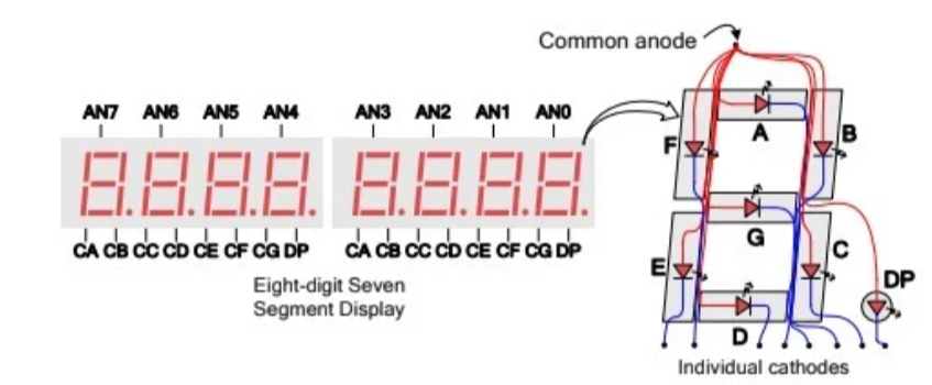
sevseg_score.v
The sevseg_score module manages the real-time visualization of player scores using the Nexys 4 DDR’s onboard eight-digit seven-segment display. Since all display digits share a common cathode bus, the module utilizes Time-Division Multiplexing to display both Player 1 and Player 2 scores simultaneously. A 500Hz clock drives an internal digit_counter, which rapidly toggles the active-low anode signals (an). In the first phase of the clock, the module enables the anode for the Player 1 digit and sends the corresponding segment data; in the next phase, it switches to the Player 2 digit. Because this switching occurs at 500Hz far exceeding the human eye's flicker-fusion threshold the two scores appear to be illuminated steadily and in parallel. The module also includes a hardware decoder that translates the 2-bit binary score into the specific 8-bit active-low patterns required to render the digits 0 through 3 on the display.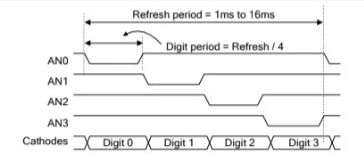
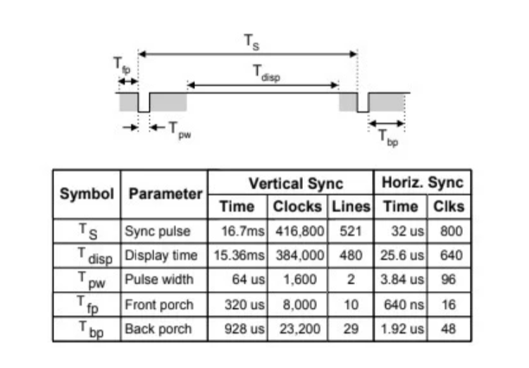
vga_controller.v
The vga_controller module serves as the critical hardware interface between the game's internal rendering logic and the physical display monitor. Driven by a 25 MHz pixel clock, the module calculates and generates the precise horizontal (hsync) and vertical (vsync) synchronization pulses required for a standard 640x480 resolution at a 60Hz refresh rate . It achieves this by maintaining continuous horizontal and vertical counters that track the exact pixel position being drawn . By exporting these live X and Y coordinates (h_counter and v_counter), it provides the overarching system with the exact spatial awareness needed to render the paddles, ball, and score in real time, while strictly ensuring RGB color data is only transmitted during the active visible display period .
renderer.v
The renderer module is a complex combinational block responsible for generating the game's entire visual presentation. It operates by evaluating the live $X$ and $Y$ pixel coordinates (h_counter and v_counter) against the internal positional registers of all game entities. While it utilizes standard Cartesian boundary conditions to draw rectangular objects like the paddles and center line , it implements a geometric squared-distance equation to accurately render the ball as a solid circle. Furthermore, the module handles hierarchical visual layering; it integrates real-time score graphics from a dedicated score_screen sub-module , and utilizes extensive hardcoded coordinate mapping to dynamically draw typography for the start menu and victory screens directly from logic gates .
score_screen.v
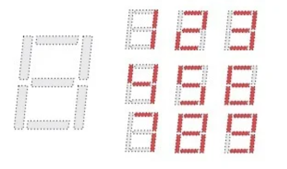
The score_screen module is a dedicated graphics sub-component responsible for rendering the players' live scores directly onto the VGA display . Instead of relying on external memory or a pre-built font ROM, this module uses combinational logic to dynamically draw block-style numbers (ranging from 0 to 3) . By evaluating the current horizontal and vertical pixel coordinates (h_counter_wire and v_counter_wire), it illuminates specific predefined visual rows and columns to form the digits, passing the resulting RGB color data back to the main renderer.
Results:
Implementing the Pong game on an FPGA using VGA output was successfully completed. The results of the project are summarized as follows:
Gameplay Performance
- Paddles respond to user inputs with minimal latency.
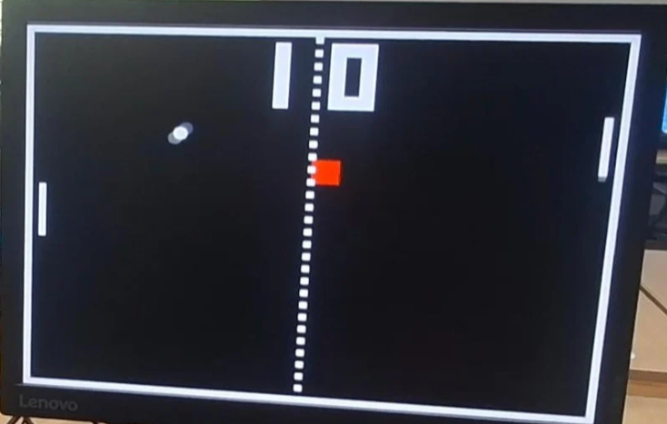
- VGA display correctly renders: Ball, paddles, borders, centre line and power-up block. Start screen, game over screen and winner text.
- Ball speed variation based on paddle contact region works correctly.
- Power-up system works correctly — paddle doubles in size and resets after 8 seconds.
- Noob mode and Boss CPU mode function as intended.
VGA Output
- Achieved 640×480 resolution at 60Hz, complying with standard VGA timing specifications.
- Color encoding was implemented successfully: Ball, paddles, borders and text are rendered in distinct white against black background.
- All game elements are mapped accurately to pixel coordinates, ensuring proper alignment and scaling across the screen.
FPGA Resource Utilization
- Registers were efficiently used for: Real-time ball and paddle position tracking.
- Game state management across all FSM states.
- VGA synchronization signals (hsync, vsync) were generated glitch-free, ensuring stable display.
Game Features
- Ball physics perform correctly with accurate wall and paddle bouncing.
- Ball speed variation based on paddle contact region functions as intended.
- Random ball direction at the start of each round is successfully generated using the LFSR module.
-
Collision detection functions correctly:
Ball-paddle contact → deflects ball back into play
Ball passing paddle → awards point to opponent
-
CPU opponent tracks ball position and responds accurately in real-time.
-
Score tracking is implemented and displayed correctly on both the VGA monitor and 7-segment display.
-
Power-up system works correctly – paddle doubles in size upon collection and resets after 8 seconds.
-
Noob mode successfully reduces speed for beginner players
-
Unbeatable CPU tracks ball more aggressively than regular CPU.
User Input and Controls
- The game supports real-time user input via push buttons on FPGA.
- The game supports real-time user input via push buttons on FPGA.
-
cpu_switch = J15
boss_cpu = L16
noob_switch = V10
pad1[1] = P17
pad1[0] = P18
pad0[1] = M18
pad0[0] = M17
Testing and Debugging:
Milestone 1: Initial ball movement
Successfully implemented basic ball motion considering collisions with walls using if-else comditions and clock-controlled updates, laying the foundation for real-time gameplay.
Milestone 2: Paddles Motion
Implemented logic for paddles motion using user inputs through push buttons on FPGA . Adding restrictions over paddle’s motion after collisions with top and bottom walls.
Milestone 3: Added classic Pong game theme
Coded the border, middle dotted line, paddles and ball as Classic Pong game theme as VGA renderer.
Milestone 4: Integration of ball and paddles with scores
IIntergrated ball and paddles motion. Displayed scores on screen and 7 seg dislay on FPGA.
Milestone 5: Added starting and game over screen
Implemented game start screen and game over screen. Game over screen will be displayed when anyone of the player scores 3 points.

Milestone 6: CPU mode added
Integrates an automated opponent logic that tracks the ball's vertical position and adjusts the left paddle's movement based on two selectable difficulty tiers, ranging from a reactive "beatable" level to a predictive "unbeatable" algorithm.
Future Scope:
1. Addition of sound
Upgrading from basic PWM tones to a dedicated DAC-based audio system for polyphonic sound effects, including distinct noises for hits, scores, and power-up activations.
2. PS/2 Keyboard Integration for Controls
Currently, direction control is handled through physical pushbuttons on the FPGA board. A more versatile approach would be interfacing a PS/2 keyboard with the FPGA to allow standard directional key inputs.
3. Advanced Physics & Multi-Ball
Implementing "spin" mechanics where paddle velocity affects the ball's bounce angle, and adding support for multiple balls simultaneously using enhanced memory tracking.
4. Pause/Resume
This feature uses a hardware clock-enable toggle to "freeze" the ball and paddle registers. This stops all movement and timers while keeping the VGA output active, ensuring a static, flicker-free image until gameplay is resumed.
References:
- IEEE snake game on FPGA - https://ieee.l2.nitk.ac.in/virtual_expo/report/76
- Basic Hardware pong - https://github.com/Amy-Liao/FPGAboard-Pong-Game
- Pong game on FPGA YouTube - https://www.youtube.com/watch?v=GeGtfDYy8bo
Repository:
All the source codes and constraints files can be found here
Mentors:
Jaya Surya
Shreyan Ghosh
Rupankar
Mentees:
Rahi Pakhale +91 9096363001
Gowrinanda R. +91 8921959816
Report Information
Team Members
Team Members
Report Details
Created: April 7, 2026, 6:49 p.m.
Approved by: Mayank Singh [Diode]
Approval date: None
Report Details
Created: April 7, 2026, 6:49 p.m.
Approved by: Mayank Singh [Diode]
Approval date: None